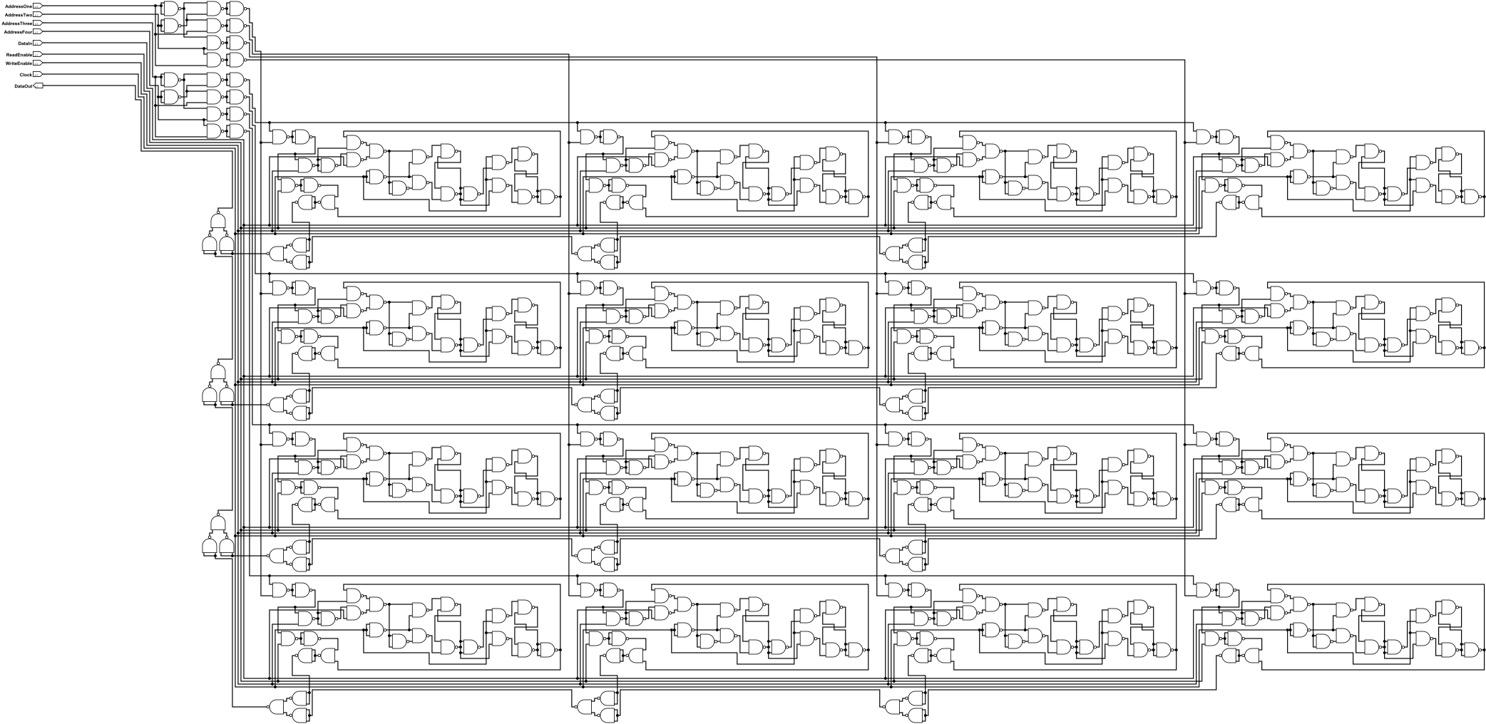
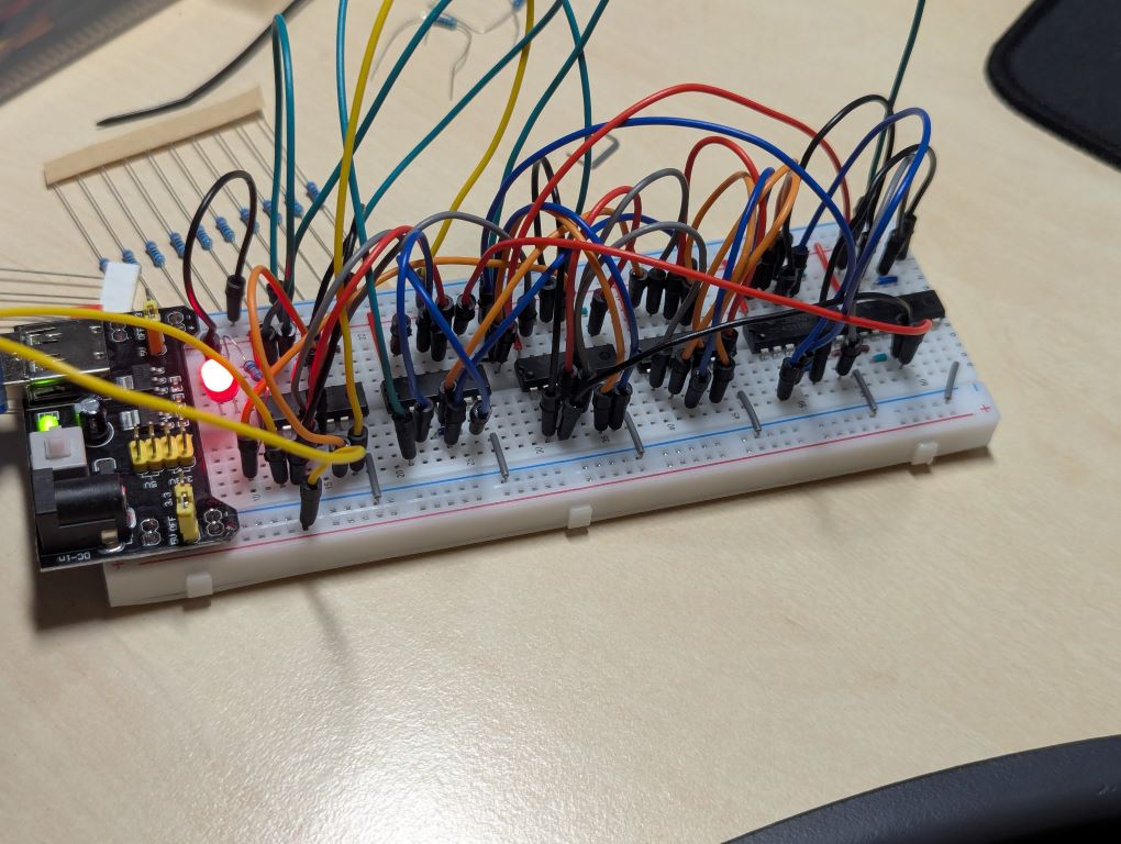
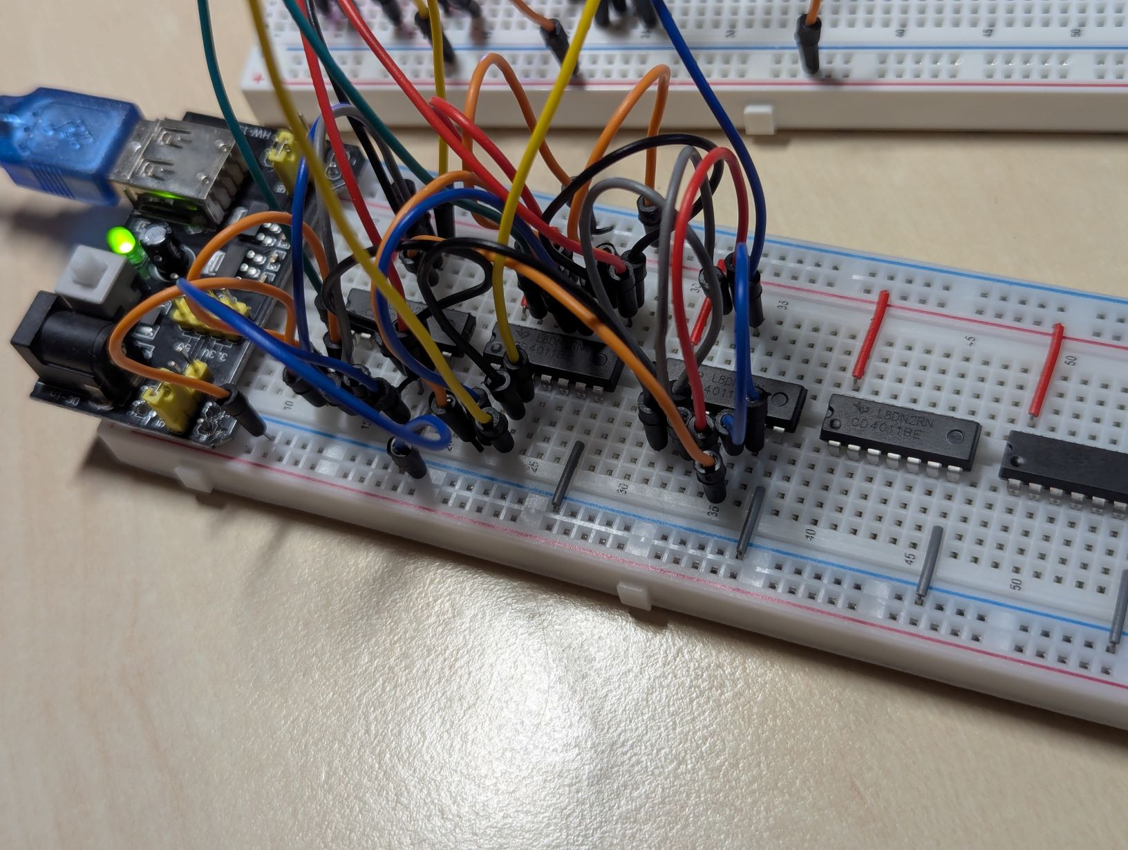
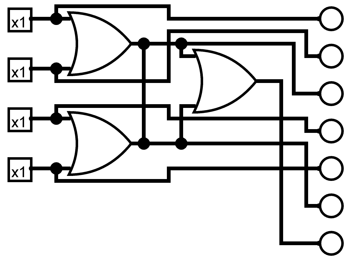
I tested having two OR gates (NAND gate combinations) outputting to the same line, feeding into a third OR gate. As you can see in the images, only the inputs of the second gate are on, but the outputs of both gates are on. This is the setup for the test. Neither input LED for the first gate is on. However, the final output LED does not turn on all the time, but only when both of its inputs are on. This suggests a voltage issue, which is also seen in the dim first output LED. The rough circuit diagram is shown (simulated in Logisim). This test will need to be redone or redesigned, as the results from this setup were inconclusive.
DIY Computer
For a few years I have been very interested in logic gates and boolean logic. From building a ripple carry adder in Minecraft, to designing RAM in Logisim, and building registers on breadboards, I love designing and implementing logic circuits. I was first introduced to logic gates in secondary school, but only at a very basic level. My interest began while studying them in my Computer Architecture module in first year of college.
Project Updates
After successfully building a one bit latch on a breadboard, I have designed and ordered PCBs with the following features:
- Stores one bit
- VCC - Voltage supply
- GND - Ground
- Address One - First bit of address
- Address Two - Second bit of address
- Data In - Single bit to be stored
- Read Enable - Flag for enabling data out
- Write Enable - Flag for enabling data in
- Clock - Pulse updates register
- Data Out - Single bit currently being stored
I substituted each logic gate in the original 16 bit register for the NAND gate equivalent, then removed redundant gates. Built and tested using a breadboard and the CD4011 IC.